
Background
For a while, we had a single set of operator controls. In our rookie year we built a driver station on which was mounted two Logitech joysticks for the driver plus an operator button-board with a couple of E-Stop Robotics CCI interface boards for subsystem controls. (It also had an Arduino to drive status LEDs, but for this post we’re going to focus on input controls only.) Simple enough. After a few years, though, things began to get complicated…
- We found that for demos, dragging the whole, large driver station assembly around was not ideal. A common refrain was, “Can’t we just bring a laptop?”
- At demos, we often wished we could have a control arrangement for one person to drive all the main subsystem controls “well enough”, rather than needing two people to operate all the controls.
- We developed another, more advanced button-board operator interface, while the old one remained in use as well.
- Some of our drivers/operators expressed a preference for handheld controllers in place of the dual joysticks, or to use handheld controllers in place of the button board.
- For offseason competitions, we needed to be able to run a 2nd robot, sometimes with different controls than it usually used. (For example, the second robot might need to use our “other” driver station, or just a laptop and controllers.)
Trying to support these sorts of variations in the software posed quite a challenge, since doing so would mean fixed mappings no longer worked. And requiring one of our programmers to go adjust the code every time there was a need to run with a different controller was not practical. We needed to be able to “plug and go” so that in situations like driver tryouts where we gave the students an opportunity to try any of the control schemes, we could swap between them quickly.
A better solution was in order.
Dividing Up The Controls
Our current controls can be logically divided into 3 groups, and some years, there may be a 4th. Currently we have:
- Driver controls: all the things that the driver is responsible for, including:
- Controlling the drivetrain
- Aiming (auto-aim button)
- Shooter ball feed
- Driver “overrides” : controls we need to support but that aren’t normally used on the competition field. In our original driver station, these were on toggle switches with flip-up “fighter pilot” covers, located on the operator’s console. These include:
- Drive Disable – for locking out the drivetrain for occasions where the robot needs to be enabled but can’t move for safety reasons. We use this in the pit a lot.
- Open Loop Drive – our normal drive is closed-loop velocity control for precision. This override runs the drivetrain open-loop instead. It’s needed for testing when the robot is on blocks on the cart, or if there’s an encoder issue that is creating a problem. (This saved us in our rookie year when we had to play a match without working encoders after a marathon emergency drivetrain repair.)
- Limelight LED disable – for rules compliance and annoyance reduction.
- Operator controls: all the things that the operator is responsible for:
- Intake extend/retract and rollers on/off
- Flywheel control
- Climber controls – deploying and climbing
The specific controls needed vary year to year, but this sort of grouping is typical. Some robots might have operator overrides too (for example, a limit override on an elevator) but our current one does not.
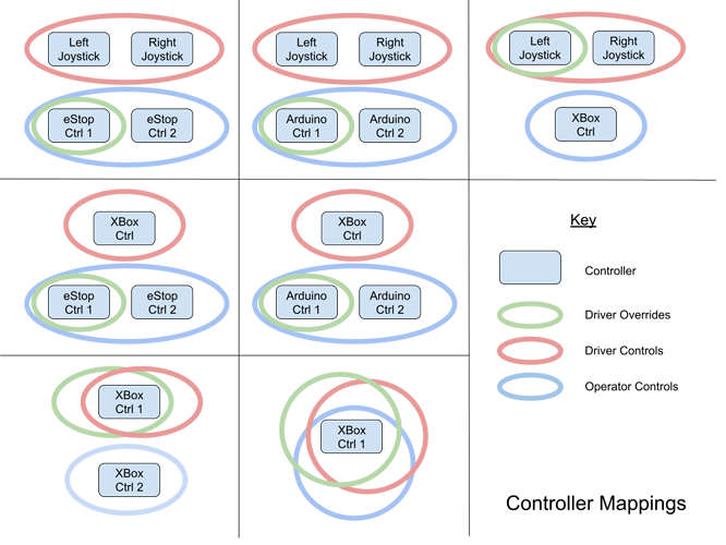
Basically, supporting flexible controls comes down to mapping these control groups, and the specific elements for each, to available physical inputs from the connected controllers. Here are some arrangements we support. If a controller is in a group, that means at least one input in that group comes from that controller.
Each arrangement requires that the specific controls within the grouping are mapped to a particular controller object and physical input (button, joystick, slider, etc.) so that the robot code can use it. This requires a fair bit of flexibility, since:
- The controls inputs represent anywhere from one to four separate controllers
- Sometimes controls groups are supported across multiple controllers (as with dual joysticks)
- Sometimes controls groups are overlapped onto one controller
- If a control isn’t available, it should be quietly unavailable without requiring special effort (or causing the code to crash)
Mapping the Concept to Software
So how do we take our concept of flexible, decoupled controls inputs and turn that into working software?
Interfaces
Representing the above in software requires some abstraction, which we provide through Java Interfaces. Each controls grouping is represented as an interface that specifies methods for getting the button for a specific function, reading specific analog controller values, and so on. Even better, Java allows us to have default methods in the interface so that if a particular implementation doesn’t support one of them, the default method provides a (dummy) version of it. Here is an excerpt from our Operator OI interface:

Here, we see a few things:
- Methods that we always expect to have implementations for, including the shooter-flywheel controls.
- Methods that might not always have implementations, like getClimbEnableSwitch, which have a default implementation that just returns a dummy Trigger. This way, if we’re on a controller that doesn’t have a mapping for that function, nothing special needs to be done; the trigger object is valid, it will just never activate.
- Interface methods that return an analog input reading. Here, the getClimbStick methods return a double value – and as before, there’s a default implementation that just returns 0.
The full interface definitions can be seen in our source code:
OI Implementations
Our code has a series of different implementations that each support one or more interfaces. Each takes one or two controller IDs and uses those to map buttons and other inputs appropriately. Depending on what controllers the main robot code detects – more on that later – it decides which implementation objects to instantiate. Some, like the “All In One”, are used alone, while others are used in combinations (for example, OIHandheldWithOverrides might be used with OIOperatorHandheld). Later, we’ll talk about how this selection logic works, but first let’s see what implementations our code currently provides:
| Implementation | Description | # of IDs | Implements Interfaces |
|---|---|---|---|
| OIArduinoConsole | Operator console based on an Arduino 32U4 that presents as 2 joysticks | 2 | IOperatorOI, IDriverOverrideOI |
| OIDualJoysticks | Dual Logitech Attack 3 joysticks | 2 | IDriverOI |
| OIeStopConsole | Operator console based on 2 eStop Robotics CCI boards | 2 | IOperatorOI, IDriverOverrideOI |
| OIHandheld | Xbox driver controller (drive only) | 1 | IDriverOI |
| OIHandheldWithOverrides | Xbox driver controller (drive and overrides) | 1 | IDriverOI, IDriverOverrideOI (extends OIHandheld) |
| OIOperatorHandheld | Xbox operator controller | 1 | IOperatorOI |
| OIHandheldAllInOne | Xbox driver controller (all functions) | 1 | IDriverOI, IDriverOverrideOI, IOperatorOI (extends OIHandheldWithOverrides) |
Let’s look at part of how one of these is constructed:


We can see that this is implementing both the operator and driver-override interfaces. Its constructor is passed two controller IDs, which it uses to build two Joystick objects. It then maps specific functions to buttons on these controllers, and provides methods for accessing these Button objects. The above is just a piece of the code to serve as an example. You can look at the code in our robot/oi folder to see the complete definition of this and the other implementations.
Finding & Using Current Configuration
On the driver station, joystick devices show up on the USB tab. The code needs to evaluate which controllers are connected, and decide based on that which OI objects to instantiate. Most important, all of the code accesses the OI through three interface objects:
private IDriverOI driverOI;
private IDriverOverrideOI driverOverrideOI;
private IOperatorOI operatorOI;
At the end of controller evaluation, all three of these need to have OI objects assigned. Because these are Interface objects, each can be assigned any object that implements that interface. This means that in some cases, they share the same object! For example:
- When the eStop console is used, both the operatorOI and driverOverrideOI use the same OIeStopConsole object. The driverOI object is separate (and could be of several types).
- When the All-In-One controller is used, all three objects are the same OIHandheldAllInOne object. This is possible since it implements all 3 interfaces!
More importantly, the code that uses these interface objects needs to know nothing about what the actual controllers are. That detail is entirely abstracted – the rest of the code simply gets and uses buttons and input values as needed, via the public methods specified in the interface.
If no mapping can be found, there is a dummy OI object that gets assigned and provides dummy methods for the things that don’t already have a default in their interfaces. This is really just a fallback to prevent crashing – it doesn’t do anything useful.
Our selection logic is in the method updateOIType in RobotContainer.java. This is called at the start of teleopInit, autonomousInit, and every 10 seconds in disabledPeriodic. This approach makes sure that controllers can be switched around and will reconfigure themselves automatically without needing to restart the code.
Selection Logic
The update method follows the basic sequence:
- Loop through connected joysticks looking for controllers that represent dedicated operator interfaces. For us, this is the eStop and Arduino controllers. If either of these is found, we know that the operator controls and driver-overrides will map to these controllers.
- Then loop through again looking for driver controllers:
- If we see a Logitech Attack 3, store it, and wait to find the second one. When we find the second one, make an OIDualJoysticks object.
- For Xbox controllers, store the first one found. If we find another, and don’t already have an operator interface, then the second becomes the operator interface.
- Then sort through other possible conditions where we don’t have a complete mapping yet. Here is where we figure out that we have a handheld driver control with overrides, or an all-in-one handheld.
- When a selection is made for operator and driver controls, a message is printed to the console to confirm what the code is using. This is very helpful when plugging and unplugging controllers!
The selection logic does, necessarily, depend on the names of the controllers and the order in which they show up in the USB tab. But this means that all students need to do is connect the right controllers and drag them to the right order (generally, driver above operator, and left joystick above right if using dual joysticks), and the code sorts out what makes sense. With some simple instructions, anyone on the team can get their desired controls working.
Pay attention to the names your devices show up as; sometimes there can be more than one representation of a specific device. An example: “Controller (XBOX 360 For Windows)” and “XBOX 360 For Windows (Controller)” are both handled in our code.
Drive Modes
To further enhance the flexibility of our controls, in addition to supporting different physical controllers, we support multiple drive modes, selectable through a SmartDashboard dropdown menu. Currently, we support:
| Drive Mode | Description |
|---|---|
| Tank | Standard 2-joystick tank-drive |
| Split Arcade | Standard split arcade (differential drive) |
| Southpaw Split Arcade | Left-handed version of above |
| Hybrid Curvature Drive | Curvature drive with automatic low speed turning |
| Southpaw Hybrid Curvature Drive | Left-handed version of above |
| Manual Curvature Drive | Curvature drive with manual low speed turning |
| Southpaw Manual Curvature Drive | Left-handed version of above |
| Trigger Drive | Xbox trigger drive (triggers for forward/reverse, steer by joystick) |
| Trigger Hybrid Curvature | Like hybrid curvature, but trigger-operated |
| Trigger Manual Curvature | Like manual curvature, but trigger-operated |
This covers pretty much all of the common drive modes and supports both right- and left-handed drivers, whatever their preference. Note as well that the drive mode is selected entirely independently of the controllers in use. The source that supports this can be found in our DriveWithJoysticks.java file.
One other 6328-specific drive feature you may see mentioned in the code is “Sniper Mode”, which we created in 2017 and have carried forward. It’s a precision maneuvering mode in which top speed is reduced to a fraction of the normal maximum, so the entire joystick analog range can be used for precise slow-speed positioning. This was ideal for placing gears on pegs in Steamworks and other similar game challenges.
Final Thoughts
We’re very glad we implemented this OI abstraction layer; it enables all sorts of flexibility that would be hard to have any other way. There is some effort involved in setting up the interfaces, and if you support as many options as we have, the selection logic can be a little complex. We think it’s worth it, though: drivers get to use the controllers they prefer, we get flexibility for testing and demos, and our primary robot code is decoupled from needing to know what controllers are in use.
As always, we’re available to answer any questions!